简单易用的OOK调制方案
Abstract: This article describes ASK/OOK techniques, and outlines implementations of ASK/OOK receivers using RF power detectors and a few discrete components. Waveform output test results of these implementations are also detailed.
A similar article appeared on the RF DesignLine website on July 21, 2008.
Introduction
Amplitude shift keying (ASK) is a popular modulation technique used in digital data communication for a large number of low-frequency RF applications. The source transmits a large amplitude carrier when it wants to send a '1', and it sends a small amplitude carrier when it wants to send a '0' in its simplest form. A further simplification of the ASK method is on-off key (OOK) modulation, in which the source sends NO carrier when it wants to send a '0'.ASK and OOK communication protocols are commonly used in short-range wireless applications, examples of which include home automation, industrial networks, wireless base stations, remote keyless entry (RKE), and tire pressure monitoring systems (TPMS). OOK is especially popular in battery-operated portable applications, as such systems can save on transmit power when (not) sending '0's. Carrier frequencies involved can vary greatly depending on the application. For example, ~2MHz is used in some low-frequency wired communications in base stations (e.g., AISG protocol), while ~433MHz is typical in short-range wireless communications that make use of the industrial, scientific, and medical (ISM) band.
Various wireless technologies, including Bluetooth®, ZigBee®, and Wi-Fi®, have made considerable headway in today's consumer world. These protocols offer means of secure communication between devices, and typically operate in the 2.4GHz ISM band using a combination of frequency shift keying (FSK), phase shift keying (PSK), and amplitude shift keying (ASK) or amplitude modulation. The security offered by these approaches includes channel hopping and spread-spectrum modes of communication. Such schemes can be difficult to overhear, offering increased security as well as improved noise immunity. All these methods spend transmit energy when sending both a '1' and a '0'. Unfortunately, these protocols also are relatively complex and have a high hardware implementation cost, especially if security and high noise immunity are not predetermined requirements.
Wi-Fi is specifically aimed at high-data-rate, wide-reaching applications and is likely considered overkill for applications requiring only simple control and monitoring. ZigBee is considered ideal for the upcoming field of sensor networks, while Bluetooth has found acceptance in a range of consumer audio devices and personal wireless devices. Table 1 provides a simple comparison of various performance features for Bluetooth, ZigBee, and ASK/OOK approaches.
Table 1. Comparison of Bluetooth, ZigBee, and ASK/OOK Features
| Features | Bluetooth | ZigBee | ASK/OOK General ISM |
| Frequency | 2.4GHz | 2.4GHz | 315MHz to 2.4GHz |
| Battery Life | Low | High | High |
| Speed | 800kbps | 200kbps | 2Mbps |
| Relative Cost | Medium | Medium | Low |
| Industry Standards | Yes | Yes | No |
Simple ASK/OOK hardware implementations have become relatively straightforward choices due to their low implementation cost in extremely long-life, battery-operated applications. They are also a good choice if access to point-to-point wired infrastructure and wireless infrared links are possible. Depending on the application, implementation costs can be 2x to 5x higher for alternate technologies. If necessary, security can still be overlaid on these links by incorporating bidirectional interrogation schemes between the transmitter and receiver, such as by exchanging a special code. ASK offers better noise immunity compared to OOK at a lower cost than FSK, but it has higher power consumption levels than OOK.
ASK Applications
ASK receiver front-ends are typically composed of three blocks: an input bandpass filter to discern the carrier frequency of interest from a broadband input noise spectrum, an envelope detector to extract the information of interest, and a comparator to obtain binary outputs. The comparator trigger threshold is derived from the output of the envelope detector itself; this enables the threshold level to autoscale with the received signal level, which can vary depending on channel length and transmitter strength.One possible implementation of a front-end uses the MAX9933, an RF power detector that can read input signals with a 45dB dynamic range from 2MHz to 1.6GHz. In particular, it delivers a logarithmic voltage proportional to a signal level between -58dBV to -13dBV (i.e., 1.25mVRMS to 223mVRMS). Figure 1 shows the MAX9933 RF detector in an ASK receiver signal chain.

Figure 1. Circuit showing the MAX9933 RF detector in an ASK application.
The RF signal fed into the RFIN pin is externally AC-coupled. Because the MAX9933 is a peak-responding RF detector, it essentially functions as a simple envelope detector, even for small, millivolt-level signals. Its log-transfer function for input RF voltage amplitude vs. output DC voltage provides a proportional-to-dB characteristic that makes the MAX9933 extremely sensitive to very small signals. Therefore, the MAX9933 allows the ASK receiver to easily discriminate between small input '1' and '0' signal levels. The value of the filter capacitor CCLPF determines the response bandwidth at the chip's output, and is thus determined by the expected data rate. Figure 2 shows the output waveform generated when the MAX9933 is tested as an envelope detector, and when the MAX9030 comparator is used with an adaptive reference to generate digital output bits. The test waveform has a 10MHz carrier frequency and a 40kbps data rate. The value of CCLPF in this test is 150pF, and the R-C filter is composed of a 100kΩ resistor and a 0.22µF capacitor.

More detailed image (PDF, 604kB)
Figure 2. Response of the MAX9933 RF-detector to an RF input signal with a modulation frequency of 10MHz at a 40kbps data rate. The two waveforms show an output response (yellow) to the input signal (blue) of (a) -10dBm and -20dBm ASK signals, and (b) a -40dBm OOK signal. The two waveforms at the MAX9030 comparator's inputs are shown in pink and green at the bottom.
OOK Applications
The MAX9930, an RF-power-detecting controller, was designed for use in a feedback control loop for power amplifiers (PA) in an automatic gain control (AGC) loop. However, when configured in open loop (i.e., without a PA to close its feedback loop from OUT to RFIN), it can just as easily be used in OOK applications, as shown in Figure 3. A REF voltage, representing a threshold well below the lowest '1' signal level received in the application, can be used to extract the OOK information.
Figure 3. Circuit showing the MAX9930 RF-detecting controller in an OOK application.
The RF signal fed through the RFIN pin is again externally AC-coupled into the chip. The front-end of the MAX9930 controller is a peak detector, and it internally detects the peak of the input RF signal. The voltage fed to the SET pin then acts as a comparator threshold, which is ideal for OOK detection. Resistors RFB and RIN provide comparator hysteresis for increased noise immunity, with RFB chosen at 300kΩ and RIN at 10kΩ; CCLPF can be minimized to increase the data rate. In Figure 4, the test results are shown with the same input conditions as in the Figure 2 test.

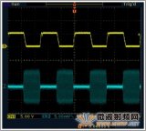
Figure 4. Response of the MAX9930 RF-detecting controller to the RF input signal with a modulation frequency of 10MHz, a 40kbps data rate, and a -40dBm OOK signal. REF is set at 500mV. Output digital bits are shown in yellow, and the input RF signal is blue.
 电子发烧友App











评论