Abstract: This article shows how to use the MAX1759 buck/boost charge pump to power white LEDs for display backlighting in portable applications.
The increasing use of color LCDs in hand-held equipment is creating a need for smaller and cheaper sources of white backlight. Cold-cathode fluorescent lamps (CCFLs) and electro-luminescent (EL) panels have been used in the past, but those circuits are excessively large, expensive, and complex for today's hand-held, consumer-electronics devices. Fortunately, recent advances in LED technology have produced an LED that emits white light. White LEDs have several advantages over conventional types, including small size, low cost, low complexity, and high reliability.
The typical forward-bias voltage for white LEDs is about 3.5V ±10%. To obtain white light you simply forward-bias the device, but a boost circuit is required because the white LED's forward voltage can be greater than the battery voltage. The conventional approach to this problem—a boost regulator that biases the LEDs through a ballast resistor—has two drawbacks. First, the wide variation of forward voltage in white LEDs causes a large variation in bias current and the resulting light output. Second, the conventional boost converter has a DC path between input and output (even in shutdown) that allows an inactive LED to drain the battery.
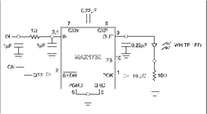
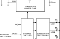
The compact circuit (Figure 1) overcomes these problems. The regulated buck/boost charge pump in a small µMAX package (U1) has a 100mA output-current capability. Configured as shown, the circuit directly regulates bias current flowing through the white LED. By biasing multiple white LEDs in parallel, it can provide good light distribution. The U1's design eliminates the troublesome input-output path in shutdown, and its active-low SHDN input (Pin 2) lets the user turn the backlight on and off. The circuit also includes a power-OK output (POK) for signaling a microprocessor when the backlight is available.

Figure 1. Unorthodox connections enable this regulated charge-pump IC to directly regulate the bias current of the white LED.
Though not necessary in this case, the input RC "π" filter limits voltage ripple reflected back to the input to just 40mVP-P (for VIN = 3.6V). Because output-voltage ripple is not visible to the eye, it is of secondary concern in this application, and allows the use of a small (0.22µF) output capacitor. Even so, the output ripple is only 400mVP-P.
A similar version of this article appeared in the March 5, 2001 issue of Electronic Design magazine.
The increasing use of color LCDs in hand-held equipment is creating a need for smaller and cheaper sources of white backlight. Cold-cathode fluorescent lamps (CCFLs) and electro-luminescent (EL) panels have been used in the past, but those circuits are excessively large, expensive, and complex for today's hand-held, consumer-electronics devices. Fortunately, recent advances in LED technology have produced an LED that emits white light. White LEDs have several advantages over conventional types, including small size, low cost, low complexity, and high reliability.
The typical forward-bias voltage for white LEDs is about 3.5V ±10%. To obtain white light you simply forward-bias the device, but a boost circuit is required because the white LED's forward voltage can be greater than the battery voltage. The conventional approach to this problem—a boost regulator that biases the LEDs through a ballast resistor—has two drawbacks. First, the wide variation of forward voltage in white LEDs causes a large variation in bias current and the resulting light output. Second, the conventional boost converter has a DC path between input and output (even in shutdown) that allows an inactive LED to drain the battery.
The compact circuit (Figure 1) overcomes these problems. The regulated buck/boost charge pump in a small µMAX package (U1) has a 100mA output-current capability. Configured as shown, the circuit directly regulates bias current flowing through the white LED. By biasing multiple white LEDs in parallel, it can provide good light distribution. The U1's design eliminates the troublesome input-output path in shutdown, and its active-low SHDN input (Pin 2) lets the user turn the backlight on and off. The circuit also includes a power-OK output (POK) for signaling a microprocessor when the backlight is available.

Figure 1. Unorthodox connections enable this regulated charge-pump IC to directly regulate the bias current of the white LED.
Though not necessary in this case, the input RC "π" filter limits voltage ripple reflected back to the input to just 40mVP-P (for VIN = 3.6V). Because output-voltage ripple is not visible to the eye, it is of secondary concern in this application, and allows the use of a small (0.22µF) output capacitor. Even so, the output ripple is only 400mVP-P.
A similar version of this article appeared in the March 5, 2001 issue of Electronic Design magazine.
 电子发烧友App












评论