Receiver Equalization
); margin-bottom: 15px; "> The basic idea behind the receiver equalization is described in Figure 5. The lossy link attenuates the forward channel data with an approximate first-order transfer function that has a much lower bandwidth than the data frequency (data frequency, fb, is equal to one-half of the bit rate). This causes deterministic jitter due to intersymbol interference. Moreover, the eye diagram at the end of this lossy cable can be totally closed for long cables. To compensate for this loss, the data is first processed through a transfer function, which is, ideally, the inverse of the cable transfer function. Hence, a sufficient bandwidth can be obtained when the link and the equalizer are cascaded. A 12-level programmable-gain approach was implemented in GMSL deserializers to prevent under- or over-boosting for different cable lengths. The gain can be set to 12 different levels of boost, ranging from 2dB to 13dB.
); margin-bottom: 15px; "> 
Figure 5. Data is equalized by applying the inverse of the channel transfer function within the receiver.
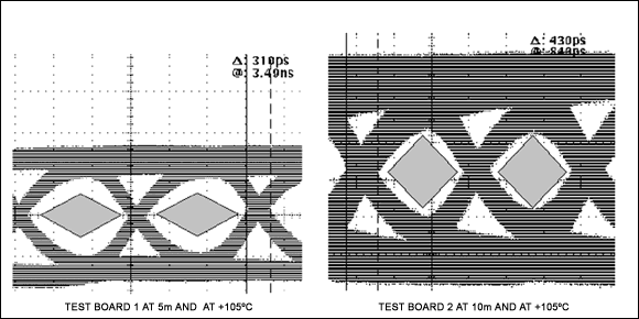
); margin-bottom: 15px; "> The receiver transfer function (AC characteristic) is shown in Figure 6 for different boost settings. The channel plus receiver transfer function are shown in Figure 7 for a 10m STP cable. Different boost levels are overlaid in this figure. The overall transfer function becomes maximally flat within the frequency range of interest when the boost word is 8 (9.4dB). The receiver input and output eye diagrams for a 10m STP cable are shown in Figure 8. Notice how the equalizer gain boost opens the totally closed eye.
); margin-bottom: 15px; "> What happens if the overall transfer function is not flat? In terms of ISI jitter, over-boosting is less harmful than under-boosting. As illustrated in Figure 9, when the boost level decreases below the optimal value, output jitter increases very quickly. Contrastingly, jitter increases slowly when the boost level increases above the optimal point.
); margin-bottom: 15px; "> 
Figure 6. Equalizer AC characteristics and boosting gain for different tuning words.
); margin-bottom: 15px; "> 
Figure 7. AC response of cable and equalizer (cascaded) for different boost levels for a 10m STP cable.
); margin-bottom: 15px; ">
Figure 8. Receiver input and output eye diagrams for a 10m cable when the boost is optimal.
); margin-bottom: 25px; "> 
Figure 9. Peak-to-peak ISI jitter vs. boosting gain for a 10m cable.
Choosing the Optimal Preemphasis and Equalizer Setting
); margin-bottom: 15px; "> Perhaps you do not want to measure the cable loss with a spectrum analyzer. In that case, the easiest method for choosing an optimal preemphasis/equalizer setting is to look at the bit-error rate of the system at limit frequencies. Two real-world cases will be supplied here as examples.
); margin-bottom: 15px; "> In Table 2, we summarize the maximum pixel clock frequencies at which our SerDes pair, like the MAX9259/MAX9260 or theMAX9249/MAX9268, can operate with a 10m cable. Each column shows a different Rx equalizer boost gain, whereas each row corresponds to a different Tx preemphasis value. The SerDes pair under testing can operate up to 124MHz when the transmission medium is equalized properly. It reaches 124MHz with a minimum total boost of 14.1dB (1.1dB preemphasis and 13dB Rx equalization). After the total boost goes above 18.2dB (14dB preemphasis and 4.2dB Rx equalization), ISI again starts to increase, which limits the operation frequency. Thus, it is wise to choose a total boost value between 14.1dB and 18.2dB. We generally recommend choosing the big portion of boost from the Rx part, because the Rx equalizer has a constant low-frequency gain, whereas Tx attenuates the low-frequency to implement preemphasis. Attenuating the low-frequency means lower signal levels over the link, which makes the life more difficult for the receiver. So 3.3dB preemphasis and 13dB Rx boost would be a good selection. The same procedure can be applied for a 15m cable as well. Its maximum frequencies for different boost levels are summarized in Table 3. Minimum and maximum boost levels are 19.7dB (8dB preemphasis and 11.7dB Rx equalization) and 23.4dB (14dB preemphasis and 9.4dB Rx equalization), respectively, so 8dB preemphasis and 13dB Rx boost is the optimum choice.
); margin-bottom: 15px; ">
| Table 2. Example 10m Automotive STP Cable and Connectors | ||||||||||||
| Rx |
0000 2.1dB |
0001 2.8dB |
0010 3.4dB |
0011 4.2dB |
0100 5.2dB |
0101 6.2dB |
0110 7dB |
0111 8.2dB |
1000 9.4dB |
1001 10.7dB |
1010 11.7dB |
1011 13dB |
| Tx | ||||||||||||
| OFF | 70 | 72 | 76 | 80 | 85 | 90 | 98 | 105 | 113 | 119 | 122 | 123 |
| 1.1dB | 78 | 80 | 83 | 88 | 93 | 98 | 105 | 111 | 117 | 121 | 123 | 124 |
| 2.2dB | 85 | 87 | 90 | 94 | 99 | 104 | 110 | 116 | 120 | 123 | 124 | 124 |
| 3.3dB | 92 | 95 | 97 | 102 | 106 | 111 | 116 | 119 | 122 | 124 | 124 | 124 |
| 4.4dB | 100 | 103 | 105 | 108 | 113 | 117 | 120 | 122 | 124 | 124 | 124 | 124 |
| 6.0dB | 110 | 112 | 115 | 117 | 120 | 122 | 123 | 124 | 124 | 124 | 124 | 115 |
| 8.0dB | 119 | 120 | 121 | 122 | 123 | 124 | 124 | 124 | 124 | 114 | 109 | 104 |
| 10.5dB | 123 | 124 | 124 | 124 | 124 | 124 | 119 | 113 | 108 | 103 | 97 | 92 |
| 14.0dB | 124 | 124 | 124 | 124 | 114 | 110 | 104 | 100 | 95 | 91 | 86 | 78 |
); margin-bottom: 15px; ">
| Table 3. Example 15m Automotive STP Cable and Connectors | ||||||||||||
| Rx |
0000 2.1dB |
0001 2.8dB |
0010 3.4dB |
0011 4.2dB |
0100 5.2dB |
0101 6.2dB |
0110 7dB |
0111 8.2dB |
1000 9.4dB |
1001 10.7dB |
1010 11.7dB |
1011 13dB |
| Tx | ||||||||||||
| OFF | 47 | 48 | 50 | 52 | 54 | 57 | 61 | 67 | 76 | 84 | 94 | 104 |
| 1.1dB | 53 | 54 | 55 | 57 | 60 | 63 | 68 | 75 | 82 | 90 | 101 | 110 |
| 2.2dB | 58 | 59 | 61 | 63 | 66 | 70 | 76 | 81 | 89 | 97 | 106 | 114 |
| 3.3dB | 64 | 65 | 67 | 69 | 73 | 77 | 83 | 88 | 95 | 104 | 112 | 118 |
| 4.4dB | 71 | 73 | 74 | 77 | 81 | 84 | 90 | 96 | 104 | 110 | 117 | 120 |
| 6.0dB | 81 | 82 | 84 | 87 | 91 | 95 | 101 | 107 | 112 | 118 | 121 | 123 |
| 8.0dB | 93 | 94 | 96 | 99 | 103 | 108 | 112 | 116 | 120 | 122 | 124 | 124 |
| 10.5dB | 108 | 110 | 112 | 113 | 117 | 119 | 121 | 122 | 124 | 124 | 124 | 124 |
| 14.0dB | 118 | 118 | 119 | 121 | 122 | 123 | 124 | 124 | 124 | 110 | 101 | 94 |
); margin-bottom: 25px; "> Color Code
| ≥ 104MHz (3.125Gbps) | 84MHz to 103MHz (2.5Gbps to 3.125Gbps) |
| 66MHz to 83MHz (2.0Gbps to 2.5Gbps) | < 66MHz (2.0Gbps) |
Link Activity Detector
); margin-bottom: 15px; "> GMSL deserializers have a signal-detector circuit, which disables the receiver when there is no signal over the link. When the signal levels are very low due to long cables or high preemphasis levels, deserializers may not detect the activity over the link. Thus, it is highly recommended to disable the activity detector, while searching the optimum preemphasis and equalizer setting for long cables (> 10m). The detector can be disabled by writing "0x80" to the byte 11 of the deserializer. It can be enabled again by writing "0x20" to the same byte after the optimum values are chosen. According to our lab measurements, the activity detector works up to 8dB preemphasis for a 15m cable at the maximum PCLK frequency 104.16MHz. There is also a low threshold option for the activity detector. It can be programmed by writing "0x00" to the byte 11. According to lab measurements, the activity detector works up to 14dB preemphasis for a 15m cable when low threshold is selected. If the cable is longer than 15m and preemphasis is 14dB, it is recommended to disable the activity detector. Cables used in these measurements are standard automotive STP cables.
 电子发烧友App











评论